Starter is important part of Motor. It not only start the motor but it provides protection from overload conditions.
(NOTE: Motor word in this post; used only for Induction motor)
One more function of starter is to limit the starting current which is only possible in star delta starter, VFDs and autotransformer starters. It is not possible to limit the starting current in DOL starter. That's why DOL is used for small rating motors only.
In this post, We will talk about the MK-1 DOL Starter made by L&T in which we will explain its Parts, Circuit diagram & Working.
DOL STARTER TYPE-MK1 BY L&T
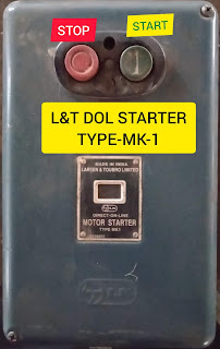 |
| L&T DOL Starter Type-MK1 |
DOL stands for DIRECT ONLINE
In this starter, motor get directly connected to power supply without any change in voltage, frequency & winding connections, That's why starter name is Direct On Line.
MK-1 DOL Starters are most widely used starter in Industry for small rating induction motors. Best part of this MK-1 starter is; its Every smallest single part is easily replaceable.
PARTS INSIDE THE STARTER
Like any other DOL starter, it consists of thermal overload relay, Contactor & push button unit. We are going to discuss all these parts one by one.
1. Thermal Overload Relay
Thermal overload relay is a protection device which protect the motor in overload conditions.
Motor's rated current depend upon the power rating of the motor that's why this thermal overload relay comes in different ampere ranges; Like 1.5-2.5Amps, 2.5-4Amps, 4-6.5Amps, 6-10Amps, 9-14Amps.
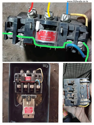 |
| Thermal Overload Relay; Type-Mk 1 MADE BY L&T |
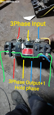
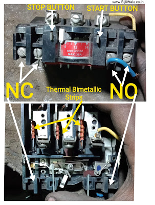
At the Top of relay; for input connections 3phase Input terminals are given out On the other hand at another side, 3phase Output+1 blue phase for HOLD is being provided.(Shown in Image below)
Thermal overload consists of NC & NO points in which NC point is used to STOP whereas NO point is used in START function. To connect the NC point with NO point RED jumper wire is being used.
BLUE wire is used for hold circuit.
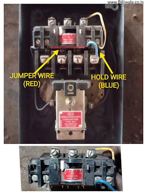 |
| JUMPER wire (Red) & HOLD wire(Blue)in Mk-1 overload Relay |
 |
| Thermal Bimetallic strips in thermal overload relay |
Thermal overload relay consists of Bimetallic strips fixed on all the three phases whenever current exceeds the limit; Bending movement of Bimetallic strips produces the trigger in NC terminal of the relay.
2. Contactor
Contactor in this starter; is a part which connects output terminals of overload relay with motor terminals. This contactor consists of plunger, Electromagnetic coil, motor terminals.
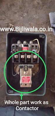 |
| MK1 Starter's Contactor |
Plunger contains 4 copper strips which are fixed with spring mechanism. These all the 4 strips having a 2 sides which connects both motor terminals & overload relay output shown in an image Below.
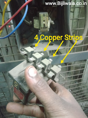 |
| Copper strips which connects motor terminal with Overload relay output |
 |
| MK-1 Starter's contactor |
Electromagnetic Coil
Electromagnetic coil is the part of contactor which lift the plunger upward when coil get energized.
Coil voltage available in 230VAC & 415VAC. In this post, the coil voltage is 415VAC.
 |
| MK-1 starter Electromagnetic coil |
Push Button Set
A pair of push button are fitted on the cover of the starter just in front of the thermal overload relay.
The pair of push button in which STOP button pushes the NC & START button pushes NO contact of thermal overload relay.
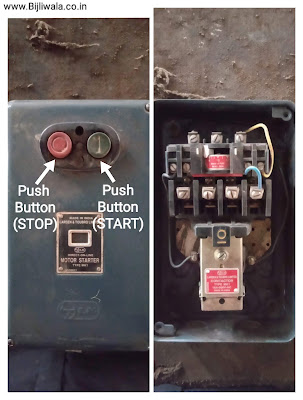 |
| Start & Stop Push Button of MK-1 Starter |
CIRCUIT DIAGRAM
Like any other Electrical panel, This starter also contains two wirings; one is control wiring and another one is power wiring. Power wiring is heavy wiring at which heavy load current flows On the other hand control wiring is light wiring at which low control current flows.
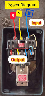 |
| Power wiring shown in Red, yellow& Blue color which starts from the top of overload relay to motor terminals |
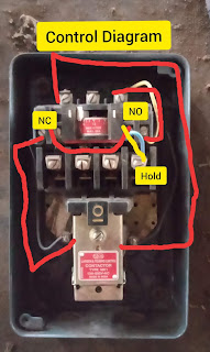 |
| Control Wiring shown in Red ! Red phase is directly connected to one side of the coil Another side of the coil passes through the NC of relay than connected at the NO contact along with blue hold wire |
WORKING DOL STARTER TYPE-MK1 BY L&T
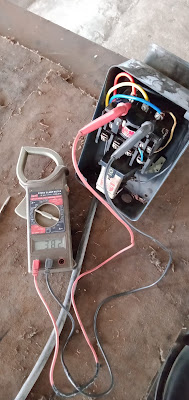 | |
|
Coil become Electromagnet which attract the plunger upward which results 4 copper strips fitted on the plunger connect the output of overload relay & motor terminals. Supply get available at motor terminals & Motor starts rotating.
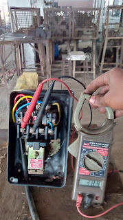 |
| Output supply at DOL Starter type-MK1 by L&T |
Since NO button is pressed only once after then NO button is being released But coil still remains energized. This all happening due the 'HOLD Circuit'.
HOLD/TRIP Circuit
Since Red phase is directly connected to the coil; we are controlling the whole circuit by just controlling the Blue phase. Overload relay contains 3 inputs & 4 output terminals, the 4th output terminal is also a blue phase.
Plunger which contain 4th copper strips; when plunger lift upward blue phase get connected through the blue wire & coil remains energized irrespective to the state of start button. When we press stop button; the NC of overload relay get break & coil get de-energized.
The tripping circuit is also uses the same NC point of overload relay. Since, current passing through the thermal relay when current exceeds the limit; Bimetallic strip produces bending movement which is used to trip the NC of the overload relay.
Hope, This post has something helpful.
For any query or suggestion you are always welcome. Please do comments !
Tags:
Induction motor starters
