FLOAT SWITCH FOR WATER TANK
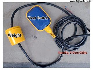
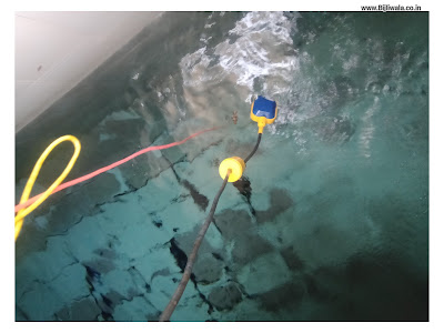
Float switch is the switch that floats into the water which actually used to control a pump or a valve. This float switch consists of hollow plastic chamber in which a limit switch is attached with mechanical lever. A cable is connected to the limit switch, most probably 3 core cable if limit switch is a changeover switch & A heavy weight is tied on the cable. (In some float switches weight is not required)
WORKING OF FLOAT SWITCH
Changeover relay is the most important component of float switch; entire working depend upon the relay that's why we need to understand the changeover relay first.
Changeover relay consists of three contacts 'Common', 'NC(Normally closed) '& 'NO(normally open)'. At initial normal state, common contact is connected with NC contact while at forced state; common contact gets connected to the NO contact. The forced state of relay can be achieve by physical force like in roller-lever limit switch or through electrical signal as in Electromagnetic relay.
When external force on relay get removed then due to the mechanical spring, common contact get pulled back towards the NC contact.
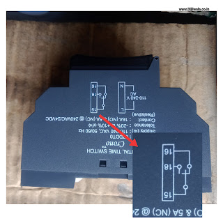 |
| Symbol of changeover relay printed on digital timer |
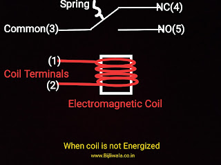 |
| Schematic diagram of Changeover relay |
Now back to the main topic which is about float switch. In metallic ball based float switch; a heavy metallic ball is placed along with a lever & a changeover relay inside the float chamber as shown in an image below. A cable which is connected to the changeover relay: brought out of the plastic chamber. The whole float chamber is IP68 ingress protected.
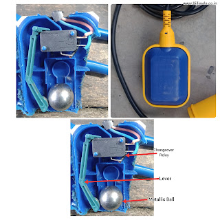 |
| Inside hollow float Switch |
At complete free fall position when water is empty & float switch is hanging freely; the metallic ball pushes the lever downward which in turn; lever presses the push button of changeover relay & relay get shifted to forced state from normal state & changes its contacts. 'COMMON' contact get connected to 'NO' contact.
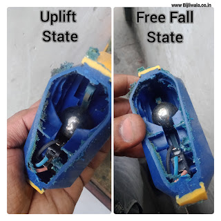 |
| Positioning of lever & metal ball inside the float switch |
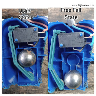 |
| Positioning of lever & metal ball inside the float switch |
On the other hand, at full water uplift position; The float switch pushed upward which results metallic ball get shifted to the opposite of lever & relay get back to its normal state Where 'COMMON' contact get connected back with 'NC' contact.
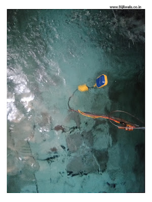
The weight which is placed on the cable of float switch; play a very important role. When float switch is hanging freely into an empty tank, Connected weight don't do anything but it works When float switch is immersed into the water.
Let suppose, We taken off the weight from the float switch & float switch is immersed into the water without weight. The float switch don't up lift completely instead it starts floating on the surface of water Which results metal ball don't able to shift its position. On the other hand, Connected weight on the cable makes float switch to lift up completely which forces metal ball to shift its position.
The length between connected weight & float switch is also important to consider which determines at what water level; float switch lifts up.
APPLICATIONS OF FLOAT SWITCH
Float switch has only a changeover relay through which we can implement multiple circuits for multiple applications. Next, we will discuss multiple applications & their circuits one by one.
Circuit to fill the tank For Single phase pump
Neutral is directly connected to the pump & Phase is passes through the 2way selector switch & 'NO' contact of the changeover relay. At these connections, When selector switch in closed position & float switch fall freely into the empty tank making the 'NO' contact closed. Pump gets power supply & starts pumping the water into the tank until the float switch get lifted up OR selector switch shifted to open position. This circuit helps to prevent overflow condition.
CIRCUIT:
.jpg) |
| Float Switch Circuit for single phase pump with automatic cut off at high level |
Circuit to fill the tank For Three phase pump running on DOL Starter
In single phase circuit, we had directly control the pump but in 3 phase we implement control circuit on contactor's coil. Motor terminals & 3phase supply is connected to the contactor. To implement tank filling circuit on 3phase pump running on DOL Starter; we just need to replace single phase motor with a 3 pole contactor with coil voltage 230VAC,50Hz.
CIRCUIT:
%20with%20contactor.jpg) |
| Float switch circuit for 3 phase pump running on DOL starter |
Circuit to empty the tank for Single phase pump
Again neutral is directly connected to the pump. Phase is passes through the selector switch & 'NC' contact of the changeover relay. At these connections, pump is used to empty the filled tank in which pump starts emptying the tank when selector switch in closed position & float switch in uplift position making the relay's 'NC' contact closed.
we can also use this circuit as a safety from dry run condition in which pump don't operate until water level is above the minimum desired level.
CIRCUIT:
.jpg) |
| float switch circuit for single phase pump to empty the filled water tank |
Circuit to empty the tank with 3 phase pump running on DOL Starter
In single phase circuit, we had directly control the pump but in 3 phase we need to implement control circuit on contactor's coil whose coil voltage is 230VAC. As we described above.
Hope, you like the post if you have any doubt, suggestion or query please do comments !

