The Electric circuit is continuous in nature, It means it has entry & exit path where current flows continuously.
(NOTE: In this post, we are defining wire bind elements as an Electric circuits such as inductive coils & resistive coils)
Continuity
Continuity is the presence of complete path for current flow. Closed & complete circuit has continuity. If we have two terminals inductive coil with terminals A&B. If inductive coil is complete without any breakage than we can say that terminal A is continuous with terminal B or we can say coil is having a continuity.
In Fault conditions, the continuity of wire or coil or heating element get break or burnt or get earthed. So that, current don't have continuous defined path to flow which results; circuit don't work. To find out the continuity; we can use 'Series Test Lamp method'.
 |
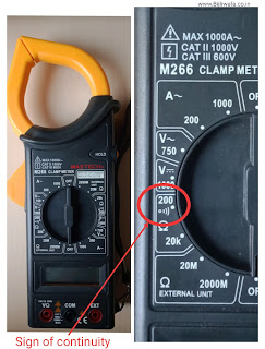
| Sign of continuity| Mastech Clamp meter M266 |
Series Test Lamp
Series Test Lamp is an arrangement of two terminals in which one terminal is phase(230VAC) & another terminal is neutral with condition that phase should passes through the Bulb (Generally Incandescent) in a series manner. (Shown in an image below)
When we short these two test terminals, bulb starts glowing with full brightness. With this test lamp method, we can find out the continuity of the circuit.
Circuit
 |
| Series TEST Lamp with 100 Watt Incandescent Bulb |
What do we find with series Test Lamp?
With series Test Lamp, We find :
- Whether circuit is continuous or not !
- Whether circuit is isolated from another circuit or not !
- Whether circuit is isolated from device body or not !
- Whether multiple circuits are identical or not !
How do we perform Series Test Lamp ?
Series Test Lamp has two test terminals, When we short these two terminals Bulb starts glowing with full brightness because of full voltage drop across the bulb. For performing Series lamp Test, we are taking an example of 3 phase Induction motor which has total 6 leads.
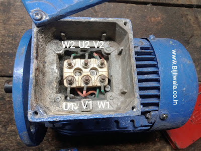
{3 phase Induction motors with 6 connection leads, In which 6 leads are provided so that we can choose the motor connections accordingly. We can operate the motor in star, Delta or in star-Delta connections. These 6 leads contains 3 winding sets which means each set has 2 terminals- U1-U2, V1-V2, W1-W2 As shown in image below}
 |
| 3 phase 2.2KW 1440 rpm Induction motor with 6 terminals ! |
At Normal working conditions
- All the 3 winding sets are equally balanced & identical with each other with identical impedances.
- U1 should be continuous with U2, V1 should be continuous with V2 & W1 should be continuous with W2.
- All the 3 winding sets U1-U2, V1-V2 & W1-W2 should be Electrically isolated from each other.
- All the winding sets should also be isolated from machine body.
•Whether Circuit is continuous OR not !
Place one neutral terminal of series test Lamp on U1 & another terminal of T-Lamp on U2.
If Bulb glows than circuit is continuous otherwise circuit is break.
Similarly, perform test on V1-V2 & W1- W2.
•Whether circuit is isolated from another circuit or not !
Place one neutral terminal on U1 & another terminal of T-Lamp on V1,V2,W1,W2 turn by turn.
If Bulb doesn't glow than circuit is isolated from another Circuit otherwise circuit is not isolated.
Similarly, perform test on both the winding sets V & W.
•Whether circuit is isolated from machine body or not !
Place one neutral terminal on Machine body(Earth) & another terminal of T-Lamp on all the 6 terminals V1,V2,U1,U2,W1,W2 one be one.
If Bulb doesn't glow than circuit is properly isolated from machine body otherwise not.
•Whether multiple circuits identical or not !
Place both the Terminals of T-Lamp on winding set U1 & U2, Observe the brightness of the bulb After then place both the terminals on V1-V2 & also on W1-W2. Observe bulb brightness on all the 3 sets.
If Bulb brightness is same on all the 3 sets than all the 3 sets are identical & balanced. If Bulb brightness is different than sets are not identical.
Where do we perform this test?
- On motor windings as explained above!
- On resistive heating coils!
- On inductive coils like solenoid coils!
- To check the continuity of any cable or wire!
- As an current limiting element for any Low voltage AC circuit !
Series test lamp as an current limiting Element
Any type of Electrical load whether it is single phase or three phase or whether it is light load or heavy; the voltage always remains same. It is the 'current & power factor' which varies according to the load(In AC). Light load takes low current while heavy load takes heavy current.
In faults conditions specially in short circuit, voltage decreases & current increases rapidly. It is the heavy current flow which damages the device in short circuit conditions.
If we have low wattage device such as 20Watt & we are not sure whether device is healthy or not. We can use series Test Lamp out there. With Series Test lamp we can operate the device, If the device is healthy than device will starts working & bulb starts glowing in a dim brightness otherwise in fault condition such as short circuit bulb glows with full brightness. In short circuit conditions, the bulb work as current limiting element & full voltage drop occur across the bulb.
(One of my own experience:
"Hand/angle Grinders which works on AC series motor whose running speed can be up to 12000rpm. Due to continuous running; Mostly its carbon brushes get deteriorated.
While detecting the fault of hand/angle grinder on direct 230Volts supply. It's always dangerous because of its high starting torque & high speed. But we can easily check the hand grinder on series Test Lamp supply because at test Lamp supply, grinder rotates at very slow rate & we can easily detect which carbon brush is not working or which part is damaged.")
Limitations
- This test Needs an Voltage source.
- Risk of Electric shock, needed to be careful while performing this test.
- Sometimes, It is difficult to Distinguish the brightness on different circuits.
Hope! You like the post. If you have any doubt, suggestion or query please do comments.


