Induction motors at starting consumes high current, this high initial current can be multiple times of rated current. In small motors less than 5.5KW, initial high current is not big concern. But for big induction motor this initial high current is dangerous.
There are multiple methods to start the induction motor like DOL starter, Star-Delta starter, VFD & Autotransformer starters.
DOL STARTER
In DOL (Direct online starter), We can't control the initial high current because it directly connects the power lines with motor terminals without any change in voltage, frequency & motor connections. That's why DOL starters are suitable for small induction motors less than 5.5KW.
Rest of the starters like Star-Delta, VFDs & Autotransformer starters have provision to control high initial current.
STAR-DELTA STARTER
Induction motors have two connections one is STAR & another one is DELTA. In STAR connection motor consumes 1/3rd current as comparing with current consumption in Delta.
Since star connection consume less current that's why to limit high initial current, motor is connected in star connection first. After some time when motor reaches its 80% of rated speed, Connection get shifted to Delta connection.
VFDs
(Variable frequency Drive)
We can easily control the speed of induction motors with through VFDs. By controlling speed we can control the initial high current by starting the motor at slow speed & increasing the speed gradually.
VFDs as name suggests, controls the speed of motor by controlling the frequency of line voltage as explained in formula below:
As synchronous Speed, Ns= (120×frequency)/poles of motor winding
Synchronous speed is directly proportional to line frequency. Speed increases when frequency increases & speed decreases when frequency decreases.
Autotransformer Starters
In autotransformer starters, variable supply voltage to motor is applied with the help of Autotransformer. Motor speed varies directly with voltage variation.
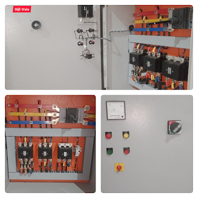
In this post, We are going to explain start-Delta starter for 75 HP motor.
Star-Delta Starter for 75HP Induction Motor
Rated current range for 75 HP motor is 100 to 115 Amps. Since current is very high, We need the heavy contactors accordingly. Since starter is star-Delta, load current got divided in half that is 55 amps if rated current is 110 amps. Starters are one time investment specially when we are dealing in big motors. Contactors must be heavy enough so that it bear the fault current.
From all point of view, we generally try to install the contactors of double of current.
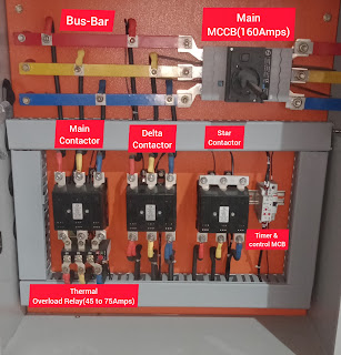
Here we are using ML-6,110Amps contactors made by L&T.
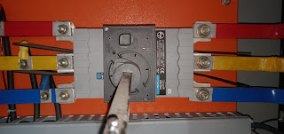
- Using 3pole;200 Amps MCCB make L&T.
- Using 3 contactors ML-6, coil voltage 415volts & current carrying capacity is 110 Amps.
- Using overload relay ranges from 45 to 75 make L&T.
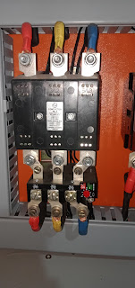 |
| ML-6 contactor; make-L&T |
- Using GIC make star-delta timer ranges from 3 sec. To 120 sec. One more best thing about this timer is, we can vary pause time between star- Delta contactor switching. Pause time ranges from 60ms to 150ms. (NOTE- Pause time must not be less than 50ms.)
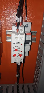 |
| Star-Delta timer| gic |
- Using Analog ammeter ranges from 0 to 200Amps. CT ratio 200/5.
- Using 35mm2 copper wire for power wiring. & 1mm2 copper wire for control wiring.
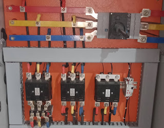 |
| Star-Delta starter |
Connection Diagram Star-Delta Starter
In star-delta starter, basic function is; start the motor in star connection until motor reaches its 80% rated speed Than switch the connection to Delta.
At starting, Star contactor + Main contactor works after that Delta contactor + Main contactor works.
Circuit Diagram
Important points for the circuit:
- Since coil voltage of contactors & timer is 415 volts. That's why we are looping one of the phase directly to coil of all contactors & timer. Another 2nd phase we are using in interlocking.
- 2nd Control phase should pass through the NC point of thermal overload relay first.
- There are NO & NC points for start & stop respectively.
- At start when we press start button, timer must be operated through the NC of main contactor.
- Parallelly with timer, STAR contactor must be operated through NC of timer's relay+ in series with NC of Delta contactor.
- Main contactor should be operated after STAR contactor.
- Delta contactor should be operated with NO of timer's relay+ in series with NC point of star contactor.
- Delta contactor should be operated when motor reaches to its 80% of rated speed.
- There should be time delay of minimum 50msec in between star & Delta contactor switching.
By considering all the 8 important points we had made a circuit diagram given below:
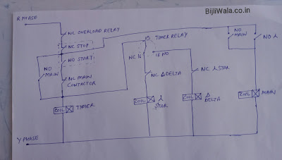 |
| Circuit Diagram STAR-DELTA Starter |
Connections for ON-OFF Remote
This starter is made for 1.5 Ton Drop forging Hammer. Panel is far away from Hammer That's why On/Off remote box must be near to the hammer. For On/Off remote, we need Push button box containing 1NO block & 1NC block. For remote wiring we also need 1(mm^2) 3 core cable.
Actually there are two On-Off remotes are working. 1one made on panel & 2nd near to the hammer.
NC contact is used for switch off function
NO contact is used for switch On function.
Both remotes NC's are connected in series. Both remotes NO are connected in parallel.
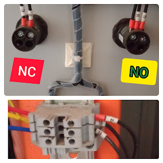 |
| On-Off push button for Star-Delta Starter |
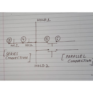 |
| On-Off remote connection Diagram for Star-Delta Starter |
Hope ! You like the post. If you have any doubt, suggestion or query please do comments.
Tags:
Induction motor starters
