Power factor is very important in Electrical field, it must be controlled at any cost. Maximum industrial load is inductive, To balance this inductive load, Capacitor banks are installed. Capacitor banks come into the circuit according to load so that a balance must be maintained in Inductive & Capacitive load.
This control of capacitors are done with the help of automatic power factor controller. Power factor controller continuously monitors running power factor & compare the running value with set value. After that Controller gives command through relay to control the ON-OFF switching of capacitors through contactors.
In this post, we are going to discuss Schneider Electric's Automatic power factor controller Varlogic RT12.
Schneider Electric's Varlogic RT-12 APFC
This product name is 'Varlogic RT' & its short name is 'RT-12'. This RT-12 represents, 12 relays for the switching of 12 capacitors.
This APFC( Automatic power factor controller) continuously monitors running power factor & compare this running value with set value after that Capacitors are controlled accordingly.
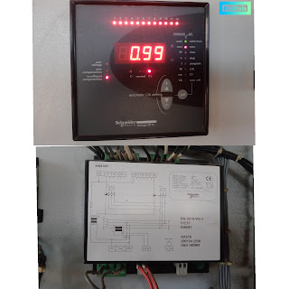 |
| Varlogic RT12 by Schneider Electric |
Along with power factor, RT also provides over Voltage protection indication, over-compensation indication & Insufficient compensation indication.
- When running load is capacitive in nature; RT shows over-compensation with the help of indication LED.
- When all the 12 steps of RT are On but still power factor is low than insufficient compensation LED glows.
RT also displays the RMS value of Voltage, Current, Active Power(kW), Reactive power(KVAR) & Apparent power(kVA).
Varlogic RT-12 Specifications
On this controller, For different indications multiple indication LEDs are being provided.
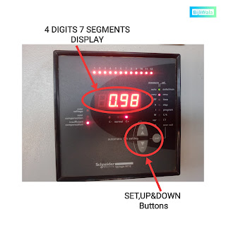
- SET, UP & DOWN buttons are provided on the controller so that we can easily change the Parameter's Setting.
- Display is 7 segments, 4 digits. For Big values Kilo & Mega LEDs are present at the side of display.
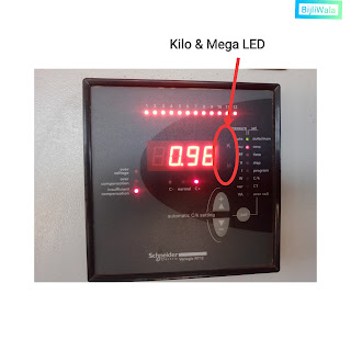 |
| KILO & MEGA LEDs ON VARLOGIC RT-12 |
- This controller is equipped with 12 relays whose present status can be displayed through 12 LEDs As shown in an image below. (Which we can say capacitor Steps)
- Relays contact rating is 3Amps/250VAC.
 |
| Over voltage, Over Compensation & Insufficient compensation alarm LEDs |
- Over voltage, Over Compensation & Insufficient compensation alarm LEDs are present on front.
- RT also displays the RMS value of Voltage, current, Active power(kW), Reactive Power(kVAR) & Apparent power(kVA).
- The status of RT whether it is in 'Normal state' or 'Capacitor is increasing' or 'Capacitor is decreasing'. All the three status are shown with three LEDs As shown in an image below.
- There is one special 'alarm relay' is provided so that some time of buzzer can be connected. This Alarm relay operates after 1 minute in Insufficient compensation & over compensation states.
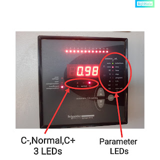 |
| Current status LEDs |
Connection Diagram for Varlogic RT-12
- RT12 Auxiliary Voltage is 400Volts. Yellow & Blue phases should be connected to controller through 2Amps fuses or MCB.
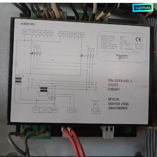 |
| Varlogic RT12 connection Diagram |
3.An Isolated transformer 400/230 volts is used for capacitor steps. The 400 volt Supply which is connected to RT12; parallelly be given to transformer primary.
On Secondary side Transformer's neutral is directly connected to all the contactors & phase is connected to common point of RT. This common point of RT connected to all the relays commonly internally.
(Phase output of transformer must be 2Amps fuse protected & neutral must be earth protected.)
Controls & Menu Operation of Varlogic RT-12
There are two things, one is 'SET the PARAMETER' & another one is 'SEE the RUNNING Value'.
- If we want to 'set the parameter' than we have to enter menu option by pressing set button for 3 sec. After than we can go through all the options by UP & Down buttons & Then select the option with set button & change the parameters with up & Down buttons. Enter the selected parameter with set button.
- If we want to 'see the running value' of power factor, voltage, Power & current etc. We just need to press UP& Down buttons. (Selected options are shown on Display & indicated with side panel LEDs.)
1.Selection of Operating mode(Auto/Man. LED)
To enter the menu option we have to press set button for 3 sec.
When Auto/man. LED is selected, operating mode changes with UP & Down buttons.
When RON is selected RT is in Auto mode.
When ROFF is selected RT is in Manual mode.
(Mode can be selected with set button)
When RT is in Auto mode, Auto/Man. LED glows continuously.
When RT is in Manual mode, Auto/Man. LED blinks. In manual mode if no button is pressed under 5 minutes it automatically shifts to auto mode.
2. COS(phi)/ Cos(phi)LED
Enter menu option by Pressing Set button for 3 sec. Then select cos(phi) LED by pressing up & down buttons. A value between .85(inductive) to 1.00 can be adjusted.
Cos(phi) present value can be seen by just Using Up & Down buttons, No need to enter menu option.
3. PF/Time LED
There are two times- response delay time (Ton on display)& reconnection delay time(TRC on display).
By Entering menu option, both the times can be changed from 10 to 1800 sec.
Factory set value of Ton(response delay) is 10sec. & TRC(reconnection delay) is 50 sec.
PF present value can be seen by just selecting PF/time LED & using UP & Down buttons, No need to enter menu option.
( NOTE- There are two terms PF & Cos(phi), theoretically both are same but for RT these values are different.
Cos(phi) is displacement power factor, related to fundamental harmonics.
PF= PF is total power factor related to all the harmonics including fundamental harmonics.
Cos(phi)= Pf ; when system is without harmonics. )
4.V/Step LED
Select step LED in menu option & set the steps. By default, RT uses all the 12 steps.
Present Voltage of the system can be seen by just selecting this LED using UP & Down buttons, No need to enter menu option.
Present Voltage of the system can be seen by just selecting this LED using UP & Down buttons, No need to enter menu option.
5. I/Program LED
RT has 11 programs of switching capacitor steps. Switching of the capacitor works according to selected program. The first capacitor must be smaller one & the next capacitors are the multiple of smaller one.
The 11 programs explained below are the ratios.
PS1- 1:1:1:1
PS2- 1:1:2:2
PS3- 1:2:2:2
PS4- 1:2:3:3
PS5- 1:2:4:4
PS6- 1:1:2:4
PS7- 1:2:3:4
PS8- 1:2:4:8
PS9- 1:1:2:3
PSA- 1:2:3:6
PSB- 1:2:4:8
For example-
Let suppose 1st capacitor is 5KVar. Then program according to PS1 becomes
PS1- 5:5:5:5
PS2- 5:5:10:10
PSA- 5:10:15:30
By selecting the particular program, RT able to understand how much reactive power is going to be connected or disconnected.
Current(I) present value where CT has been installed can be seen at this LED by just using UP & Down buttons, No need to enter menu option.
6.W/ (C/k)LED
The C/k value is a threshold value for switching ON/OFF the capacitor steps.
This value RT can calculate automatically or we can also feed this value manually.
C/k value is equal to the ratio of 1st capacitor KVAR & CT ratio
Let suppose 1st capacitor is 5kvar & CT ratio is 200/5
C/k value becomes- 5/(200/5)= 0.125
The present value of active power/true power by this LED by just using UP&DOWN buttons, No need to enter menu option.
7.Var/CT Led
Select CT LED in menu option & set CT ratio. CT ratio up to 10000/5 can be selected.
Present value of Reactive power of the system can be seen by just using UP & DOWN buttons, No need to enter menu option.
8. VA/Over volt
Select Over Volt LED in menu option & select Over Voltage range which is 180-265Volts or 320-460Volts or Disabled.
Present value of Apparent power can be seen by this LED by just using UP & DOWN buttons, No need to enter menu option.
Summary
- Varlogic RT 12 is overall a very good Automatic power factor controller. All the values whether it is CT ratio value, cos(phi) value, step value- all the values can be seen & changed easily.
- It continuously indicate the status of RT whether it is increasing capacitor or decreasing capacitor or in normal stable condition.
- It also indicate about Over compensation & Insufficient compensation states.
- It also equipped with over Voltage protection.
- 1 special alarm relay is being provided.
Hope ! You like the post if you have any doubt, suggestion or query please do comments.
Tags:
Power factor

EVERYTHING IS WELL EXPLAINED, GOOD JOB !
ReplyDeleteThank you brother for this post. It help me alot to understand this product.
ReplyDeleteThank for the comment,Sir!
DeleteDC link capacitors This particular is usually apparently essential and moreover outstanding truth along with for sure fair-minded and moreover admittedly useful My business is looking to find in advance designed for this specific useful stuffs…
ReplyDeleteYou can order such products from here hobby electronics store near me
ReplyDelete