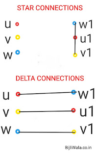
Maximum industrial motors are Induction motors, That's why it is important to study every aspect of induction motor like; it's starting, running and protection.
Starters employed for motors not only to start the motor but it provides protection to the motor in overload & phase loss conditions.
For small rating motors up to 7.4 kW, DOL starters can be employed. But above 7.4 kW, DOL is not good choice specially when load directly connected to the motor because starting current can't be controlled through DOL starter; As starting current of motor may reach up to 8 times the rated capacity of motor in DOL.
High starting current can deteriorate the motor winding by producing electrical stress which further reduces the useful life of the motor. & one more big problem is associated that is, For overload protection overload relays have been connected but due to high initial starting current overload relay always trips at starting in DOL starters.
Actually there are two reasons:
Reason No.1 (BIG REASON)
At starting, there is no back emf generated in the winding that's why extra initial current exists.
To limit the high initial current in induction motors, Several starting methods been employed for example- Star-Delta starters, VFDs, Auto transformer starters. From all the methods, Star delta starter is easier & cheapest one. In this post, we are going to discuss star-Delta starter.
Star Delta Starters
 | |
|
 |
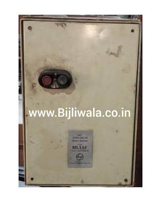
| Star-Delta Starter| ML 1.5 By L&T |
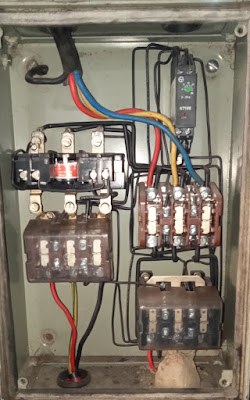
Components of Star-Delta Starter
- 1st contactor work as a main contactor.
- 2nd contactor work as a star while 3rd work for Delta connection.
Motor's 3 terminals are directly connected to the main contactor. Remaining 3 terminals are connected to star and delta contactors parallelly. At time of starting motor runs in star connection In which Main+ Star contactor works. After some time star connection get changed in delta connections & star contactor get exchanged with delta contactor in which Main+ Delta contactor works.
 |
| Components of star-Delta Starter |
Wiring of Star-Delta Starter
There are many circuits for Star-Delta starters but function remains the same. In which at the time of start when we press ON button; star contactor & timer Energizes first after that main contactor energizes. Next, According to the set time on timer, star contactor eliminated & Delta contactor comes into the circuit while main contactor continuously remains in the circuit.
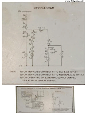 |
| Key Diagram Star-Delta Starter| MK1.5 By L&T |
- Since coil voltage of all the contactors is 415 volts that's why one phase X1 is directly connected to all the three contactor coils and timer. While Another X2 phase is used in control circuit.
- X2 phase passes through the NC of stop button after that it is connected to NO of start button.
- When we press start button, supply passes through the NC of Delta then NC of timer & then connected to the timer. In parallel with timer, Star contactor in series with NC of main contactor is connected.
- Timer & Star contactor get energized. Star contactor get a HOLD from its 43-44NO which is connected in series with NC of Main contactor.
- After star contactor, 23-24NO of Star get closed which results main contactor(H) get energized. Main contactor get a Hold from its 43-44NO.
- According to the set time on timer; When timer relay operates its 4-5 NC get changed & Star contactor & timer both cut out from the supply. In the mean time, Main contactor still energized.
- After the cut out of star contactor & timer, Delta contactor get a supply through NC of Star & NC of timer.
- This circuit; Main contactor & Delta contactor hold until 95-96NC stop button is pressed or motor trips or power supply get cut out. Actually, the overload relay also using the same 95-96NC in tripping.
- 11-12NC of main contactor is used so that star contactor Energized only when Main contactor is not Energized; at the time of starting.
- 11-12NC of Delta contactor is used so that star contactor & timer operates only when Delta contactor is not Energized. In Reverse we can also say that when Delta contactor operates this 11-12NC of Delta contactor completely eliminate the Star contactor & Timer from the circuit.
- Supply to Delta contactor passes through the series combination of 11-12 NC of Star contactor & 9-8NC of Timer so that Delta only operates when star contactor & timer both are OFF; not energized.
- At last, Main 95-96 NC is used in stop button & As a NC of overload relay.
HOPE ! you like the post. If you have any query or doubt please do comments. You are always welcome.
