In Industry, Angle grinder play a very important role. Many tasks such as cutting, grinding, polishing can be done easily with this small comfortable machine. Maximum industrial motors are Induction motors which run at a maximum speed of 2800 rpm at 50Hz frequency But these small hand held grinders can run from 5000 to 12000 rpm which is high, Very High.
In this post, We are going to explain the working & configuration of Angle Grinders.
ANGLE GRINDER
Angle grinder is also known as disc grinder or hand grinder. This hand held machine through which cutting, grinding & polishing can be done by just changing the working wheel.
This machine comes in different shapes, sizes & power ratings. Size of this angle grinder relate with the size of wheels which comes in 4",4.5",5",6"& 7"(inches). This size is actually the diameter size of the wheel running on grinder.
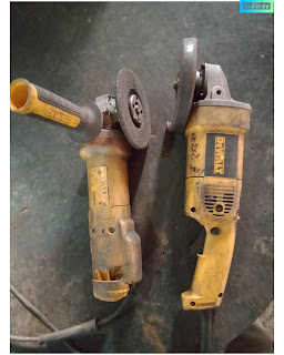 |
| Angle Grinder by DEWALT (Left Grinder 4"/ Right Grinder5") |
PARTS OF ANGLE GRINDER
This Machine is actually an AC powered series induction motor in which field winding works in series with armature winding. A same current flows through the both field winding & armature winding.
This motor is also known as universal motor because it can work on both AC as well as DC supply.
Next, we are going to discuss the parts of machine one by one !
- Field winding
Field winding is the stationary part. In this winding; two coils with equal turns; are arranged opposite to each other & rotor rotates in between the field windings. While running it produces lot of heat due to the core loss(eddy current loss & hysteresis loss) that's why field winding is fully laminated to minimize the loss.
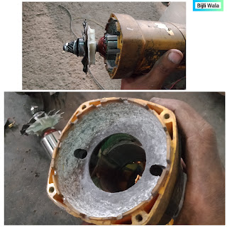 |
| Field winding of angle grinder |
- Armature (Simply can say a ROTOR)
It is the rotating part of the grinder Which also carries winding. The winding ends are connected to the commutator. (Commutator is round arrangement of copper strips on which armature wires are soldered.)
To hold the armature freely in the center, Bearings are installed on both the sides of armature. A special laminated insulation is layered up on the armature winding due to which full armature seems like a single solid piece. A cooling fan & small gear is also fitted on top of the armature which we can see in an image below.
 |
| Armature of angle grinder |
- Carbon brush
Since armature is rotating part. To pass the current through the armature, A carbon brush mechanism is adopted in which carbon brush rub against the commutator strips. Carbon brushes are made up of soft graphite material so that no harm happens to commutator. These carbon brushes are highly resistive & provides high resistance to the circuit.
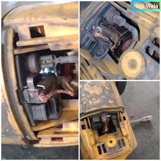 |
| Carbon Brushes fitting inside the angle grinder Carbon brush rubbing against the commutator(image Left) |
- DPST Switch (Double pole single through Switch)
For ON- OFF purposes, DPST switch is provided. This switch contains 2 poles, Both the poles are been operated through a single switch. Grinder works when DPST switch is pressed. For continuous operation, a switch lock is also provided to lock the DPST switch. |
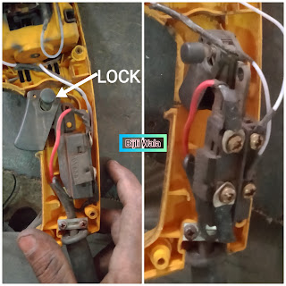 |
| Hand grinder's DPST switch |
- Gear head assembly
A gear assembly is provided on the head of grinder at which working wheel is mounted. A small gear which is mounted on the armature shaft which transmit the rotating power to gear head assembly.
For changing the working wheel, A lock is provided on gear head assembly which is used to dismantle the working wheel easily.
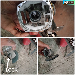 |
| Gear head assembly of angle grinder |
WORKING PRINCIPLE OF ANGLE GRINDER
Whenever A current carrying conductor placed in magnetic field; torque get produced.
Armature which is placed in between the field windings. Power supply when applied, field winding becomes electromagnet. Since field winding is in series with armature winding, At the same time armature behave as a current carrying conductor which results torque get produced. This torque rotates the grinder in a fixed direction.
The direction of rotation always remains the same because same current flows through field & armature winding. Even in case of supply reversal rotation remains the same because change of supply occurs in both the windings simultaneously.
WIRING DIAGRAM OF ANGLE GRINDER
Phase & Neutral both passes through DPST switch first. Phase & neutral, Both the wires are connected to each end of both the field windings & another terminal of field winding connected to carbon brushes. At last, armature is placed between the carbon brushes.
This whole wiring constitute a series connection. First current passes through the field winding, then through carbon brush & motor's armature then through another carbon brush & at last through the another field winding.
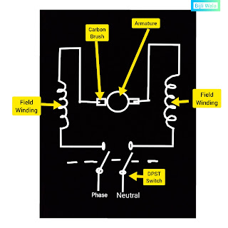 |
| Angle grinder's Wiring Diagram |
SUMMARY OF ANGLE GRINDER
- Angle grinders are compact powerful high speed machines with running speed ranges from 5000rpm to 12000rpm.
- Angle grinder is basically a AC series motor that are also known as universal motor.
- Rotor of this machine contains winding which is known as Armature.
- The rotor(armature) rotates in between the field windings.
- To pass the power through the rotor, carbon brush & commutator method is adopted, Carbon brushes are been pressed against the commutator.
- After long run carbon brushes get deteriorated which further needs a replacement.
Hope you like the post! If you have any doubt or suggestion please do comments. Your comments are valuable to us.
Tags:
Electrical Machines

Can an Angle Grinder Cut Concrete?
ReplyDeleteTechnically No !
DeleteIt is not safe & easy to use angle grinder on concrete.
For concrete cutting there are concrete cutters available which are safe & easily to use.
Can you change the direction of turn by exchanging the carbon brush end with polarity end on both the two field windings ?
ReplyDeleteNo, Direction of rotation will not change by changing the carbon brush ends.
DeleteThis comment has been removed by the author.
ReplyDeleteMotor rating is 0.6 KW. The motor which is used in this; is series induction motor. Which is specially designed for these type of applications.
ReplyDelete