"NO & NC Contacts- the Building Blocks in Electrical system!"
One of my college professor had spoken the above statement. He also said Electrical system is standing on these two blocks.
At that time, I didn't take it seriously. But now, I know the importance of these very well. I myself using these building blocks to create a logic in Electrical system.
'NO & NC Contacts' What are they? Where & How, We are using these in Electrical system. All of these, We are going to explain in this post.
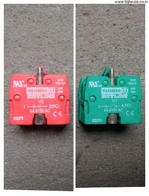 |
| Push button blocks NC(left)-NO(Right) |
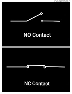 |
| Symbols of NO & NC Contacts |
What are NO & NC Contacts ?
NO Stands for 'Normally Open'
NC Stands for 'Normally Closed'
Normally means 'at initial state', 'a stage without operation' or 'a default state'.
NO represent a switch which is open at default state or at initial state. But when this switch get pressed, the open contacts of NO get closed. After than if we release that switch, it comes back to its initial open state.
 |
| Symbol of NO Contact |
NC represent a switch which is closed or connected at default initial state.
When this switch get pressed, the closed contacts of NC contact gets opened. Further if we release that pressed switch; it regain its initial closed state.
 |
| Symbol of NC Contact |
How these duos are being used ?
From a basic Circuit to big complex circuits, NO & NC contacts play a very important role.
A simple BELL Switch is the Best example of NO contact in which contact closes only when we press it. After than switch again retain its initial NO state when switch get released.Refrigerator's door light switch is the NC Contact. When we open the door of refrigerator; the switch get unpressed & switch's contact get closed at that stage which results light get ON. On the other hand, when we close the door; switch get pressed & become Open which results light get OFF.
Next, we are going to explain some of the examples Where & How these duos are being used.
IN MOTOR STARTERS
We are taking an Example of DOL Starter
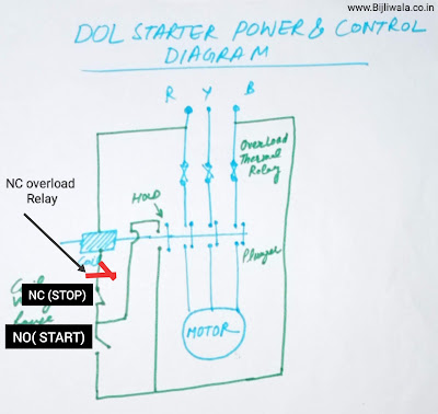
DOL stands for Direct ON Line. It is the most important starter for small rating induction motors. It's circuit is very simple & easy to understand.
 |
| Wiring Diagram of DOL Starter |
In this circuit, NC contact is used at two places. 1st NC used for stop button & 2nd NC for overload protection. Both the NC's are connected in series.
Whereas NO is used in start button & in hold circuit.
Actually, Contactor's 3 main power contacts are also NO contacts.
Similarly, combination of NO & NC is being used in other starters.
IN CREATING LOGIC
In Electrical, Logic is a wired or digital program which in combination with inputs produces output.
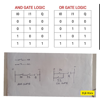
To explain the use of NO & NC contacts in creating logic we are taking an example of logic gates. Output & Input, both have probability of two states which is either 1(High) or 0(low). The output state entirely depend upon the logic in combination with state of the inputs. These logics gates; we can also implement in Electrical system with little assumptions, Like
- At Input side 1 means switch is Pressed & 0 means unpressed.
- At Output side 1 means output is ON & 0 means output is OFF.
We are taking an example of logic gates with 2 inputs & 1 output.
- Explaining AND Gate
In And gate if we look at its table as shown in an image below, Output is ON only when both the switches are pressed. Rest of the cases output always remains OFF.
This logic can be obtain if both the NO contacts are connected in series.
- Explaining OR Gate
In OR Gate, Output is OFF only when none of the input switch is pressed. Rest of the cases, output remain ON whether 1 switch is pressed or both the switches are pressed.
OR gate can be obtain if both the NO contacts are connected in parallel.
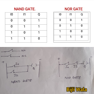
NAND gate is the inverted gate of AND.
In NAND gate output is off only when both the inputs are pressed, this can be achieve by connecting both the NC contacts in parallel.
- Explaining NOR Gate
NOR gate is the inverted gate of OR Gate. In this gate, Output is ON only when none of the input is pressed. This is possible when both the NC blocks are connected in series.
 |
| NAND & NOR logic Gate |
In above examples, we have seen that we can obtain entirely different output by using two input contacts. We can easily built any type of electrical circuit by using these NO & NC contacts.
USE IN RELAYS
Relay is the device which electromagnetically or Electronically control the circuit when a signal is given to it.
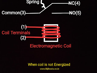
For this, We are going to explain 5 pins electromagnetic changeover relay. In which 1st & 2nd pins are coil's pins, 3rd pin is common, 4th pin is NC & 5th pin is NO.
 |
| 5pins Electromagnetic changeover relay when coil is not energized. |
As shown above, at normal state when coil is not energized; common pin is connected to NC with the help of spring. But when coil get energized, Electromagnet pushes the common pin towards the NO pin.
(Common pin- Common is the point which carries the required signal at required voltage & connects to either NO or NC at a time.)
In above example we are controlling only 1 function with 1 signal.
Next is; 14 pins relay which controls 4 functions with only 1 signal. This 14 pins relay contains only single coil with 2 pins for coil Rest 12 pins constitute 4 relays with 3 pins each. All the 4 relays work united simultaneously.(4×3=12)
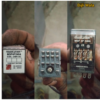 |
| Electromagnetic Relay 14pins by SALZER |
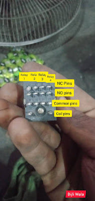 |
| Pins Description of 14 pins Electromagnetic relay |
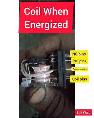 |
| 14 pins Electromagnetic relay when coil is Energized |
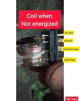 |
| 14 pins Electromagnetic relay when coil is not Energized |
With the help of 14 pins relay, we can control multiple functions with 1 signal, This makes easy for us to create logic.
USE IN DEVICES AS A RELAY
Time, Temperature are the most important parameters in industry that's why for production improvement devices like Timers & Temperature meters are being employed. These devices continuously monitors the input signal & control output according to set parameter through the relay fitted in them.
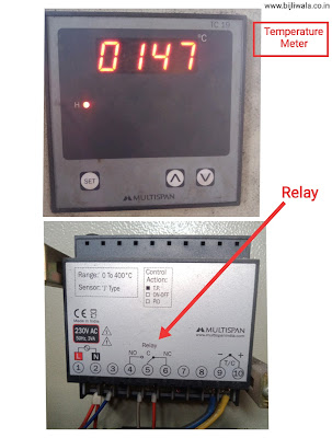 |
| Temperature meter Range(0-400°C);Type-TC19 Made by MULTISPAN |
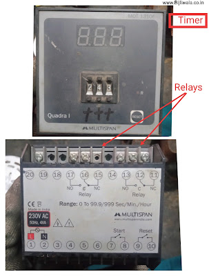 |
| Timer with 2 Relays; Type- MDT 1310F Made By MULTISPAN |
USE IN PROGRAMMABLE DEVICES
Programmable devices like PLC & Programmable HMI connected with multiple inputs & outputs.
In Some cases, signal voltage of input devices is not same as the input voltage required in programmable devices that's why relay cards with NO contacts are being used.
Similarly at output side, PLC give command through relay cards.
To isolate the programmable devices from external circuitry, relays with NO & NC contacts are very important.
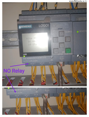 |
| Outputs connected at PLC through relay's NO contacts| SIEMENS LOGO ! |
Conclusion
- NO & NC contacts are real building blocks in electrical system.
- Bell switch is the simplest example of NO contact which connects when switch get pressed.
- Refrigerator door's light switch is the simplest example of NC contact which connects when switch remains unpressed.
- From simplest logic to complex programming in programmable devices everywhere These contacts play very crucial part.
Hope! You like the post if you have any doubt, suggestion or query please do comments.
Tags:
Basics of Electricals
